
Tutorial-1 LED Interfacing with Arduino

Introduction:
To get started with designing mega projects or electronics innovation the understanding of basic and simple projects is important. This will get familiarized with Arduino Microcontroller and also the designing environment. LED Interface Arduino UNO is one of the basic projects. Therefore, shall be looking at the very basic project which is interfacing LED with Arduino.
Arduino UNO has built in LED (Light Emitting diode) available at digital pin no. 13. This built in led is very useful if want to show some signal without connecting external LED. Meanwhile can connect LED externally by using the resistor in between the digital pin of Arduino to the LED. While connecting the LED with the Arduino make sure know the resistor value required, will also discuss in this tutorial how to calculate the resistance required for LED. After finding the correct value resistor, interface the LED with Arduino. For a single LED required digital output from the Arduino, digital pin 13 for interfacing the led with Arduino and will connect the LED in forward bias. Means LED’s anode to the pin no. 13 and cathode to the GND of the Arduino.When using external LED to the Arduino board, should connect the proper value resistor to the LED to limit the current coming from the Arduino UNO pin. A led requires around 10-20mA of current but Arduino pin gives around 40mA, so due to excess current LED may damage. For protecting LED need a current limiting resistor.
Working principle of the project:
This is a simple project which will make LED blink. The basic idea is to turn on LED and after some time turn it off. The anode of the LED is connected through a 330 ohms resistor to pin 13 of Arduino and the cathode also through the 330 ohms resistor to GND. When the command to turn on the LED is given through code, a +5v is supplied to the anode of the LED and this makes it light up. Also when the command to turn off the LED is given, it takes it back to 0v thereby turning the LED off. The code is given below.
Table of Content:
1.List of Inventories
1.1 Hardware Requirements
1.2 Software Requirements
1.3 Brief Introduction of component and calculate resistance
2. System Modelling
2.1 Circuit Diagram,Schematics and PCB design
2.2 Source Code Programming
2.3 Blink LED with programming
2.4 How to get .hex file
2.5 Detail explanation of code
3. Result
1.List of Inventories:
1.Hardware Requirements:
1.Resistor: 220ohm
2. Light Emitting Diode: 5mm
3. Power Supply: 9v and <=1A (For Arduino)
4. Connectors: (Male to female)
Development Board:
1.Arduino or Genuino UNO
1.2 Softwares and Library:
1.2.1 Arduino Software:
1.2.1.1 Arduino for MAC
1.2.1.2 Arduino for Linux
1.2.1.2.1 For LINUX 32-bit
1.2.1.2.2 For LINUX 64-bit
1.2.1.2.3 For Linux ARM
1.2.1.2.4 For LINUX ARM64
1.2.1.3 Arduino for Windows
1.2.2 Proteus Software:
1.2.3 Arduino Library for Proteus:
1.2.4 Genuino Library for Proteus:
1.3 Brief introduction of the components
1. Arduino UNO

Arduino is a simple to use microcontroller board used in most engineering projects where automation is needed. IO devices like Sensor, modules and many others things can be interfaced with the Arduino board to accomplish a task. Arduino is an open source board which means that all the design specifications, schematics, and software library are available openly for all users. The Arduino board has gained popularity today among many hobbyists because it is friendly and easy to use and can be used to design complex projects. It can be easily programmed using its own software; the Arduino IDE. The nature of the Arduino language is friendly and makes it easy for everyone to develop prototypes and hardware to suit their intended purpose.
What is Arduino?
Arduino is an open-source electronics platform based on easy-to-use hardware and software. Arduino boards are able to read inputs – light on a sensor, a finger on a button, or a Twitter message – and turn it into an output – activating a motor, turning on an LED, publishing something online. You can tell your board what to do by sending a set of instructions to the microcontroller on the board. Over the years Arduino has been the brain of thousands of projects, from everyday objects to complex scientific instruments. A worldwide community of makers – students, hobbyists, artists, programmers, and professionals – has gathered around this open-source platform, their contributions have added up to an incredible amount of accessible knowledge that can be of great help to novices and experts alike.
Why Arduino?
Thanks to its simple and accessible user experience, Arduino has been used in thousands of different projects and applications. The Arduino software is easy-to-use for beginners, yet flexible enough for advanced users. It runs on Mac, Windows, and Linux. Teachers and students use it to build low cost scientific instruments, to prove chemistry and physics principles, or to get started with programming and robotics. Designers and architects build interactive prototypes, musicians and artists use it for installations and to experiment with new musical instruments. Makers, of course, use it to build many of the projects exhibited at the Maker Fair, for example. Arduino is a key tool to learn new things. Anyone – children, hobbyists, artists, programmers – can start tinkering just following the step by step instructions of a kit, or sharing ideas online with other members of the Arduino community.Arduino also simplifies the process of working with microcontrollers, but it offers some advantage for teachers, students, and interested amateurs over other systems:
Inexpensive – Arduino boards are relatively inexpensive compared to other microcontroller platforms. The least expensive version of the Arduino module can be assembled by hand, and even the per-assembled Arduino modules cost less than $50
Cross-platform – The Arduino Software (IDE) runs on Windows, Macintosh OSX, and Linux operating systems. Most microcontroller systems are limited to Windows.
Simple, clear programming environment – The Arduino Software (IDE) is easy-to-use for beginners, yet flexible enough for advanced users to take advantage of as well. For teachers, it’s conveniently based on the Processing programming environment, so students learning to program in that environment will be familiar with how the Arduino IDE works.
Open source and extensible software – The Arduino software is published as open source tools, available for extension by experienced programmers. The language can be expanded through C++ libraries, and people wanting to understand the technical details can make the leap from Arduino to the AVR C programming language on which it’s based. Similarly, you can add AVR-C code directly into your Arduino programs if you want to.
Open source and extensible hardware – The plans of the Arduino boards are published under a Creative Commons license, so experienced circuit designers can make their own version of the module, extending it and improving it. Even relatively inexperienced users can build the breadboard version of the module in order to understand how it works and save money.
2. LED

LED (Light Emitting Diode) is a P N junction diode which emits light when activated. It is activated when the PN junction sustains a forward voltage (forward bias), a current from P to N, called forward current. When this current is applied, electrons recombine with electron holes within the device thereby releasing energy in form of light. LED finds application in traffic signals, lighting, camera flashes etc. The way to distinguish between the positive and negative terminal is, the positive is longer than the negative in length.
2.1 How to Calculate the Led Resistance
By using this formula we
find the resistance value used across the led.Led resistor value can be
calculated by Ohm’s law:
R=(V s-V led)/I led
where:
V s is the source voltage, measured in volts (V),
V led is the voltage drop across the LED, measured in volts (V),
I led is the current through the LED, measured in Amperes (Amps/A), and
R is the resistance, measured in Ohms (Ω).
Example:
V s= 5V
V led= 1.8V
I led= 20 mA = 0.02A
R = 160 ohm
From the calculation, we get 160 ohms.
but roughly we use around 100 to 1 K ohm resistor. Only LED’s intensity will vary.
2. System modelling:
2.1 Circuit Diagram, Schematics and PCB Design:


2.2Source Code programming:
2.1.1 Blink LED with Arduino
Open the Arduino IDE and write the following program to blink an LED. I have written the blink (File -> Example -> Basic -> Blink) example provided in the book Getting Started with Arduino. You may see the screenshot below. After writing the program you may save it with a file name of your choice (find File–>Save on menu bar of IDE)

Now we have to load the program from the PC to our Arduino board. To do this perfectly, you have to ensure the following steps.
STEP 1 – Selecting the board
You have to select the Arduino board type in your IDE. I am using an Arduino UNO board. To choose the board, find Tools on menu bar. Choose the option “Board” – and select your correct Arduino board. I have chosen Arduino UNO. See the screenshot.

STEP 2 – Select the right port
The port number is assigned while installing the hardware driver of board. You may refer the tutorial on Installing Arduino on Windows to know how to find the port number of board. You can find the port number by accessing device manager on Windows. See the section Port (COM & LPT) and look for an open port named “Arduino UNO (COMxx)“. If you are using a different board, you will find a name accordingly. What matters is the xx in COMxx part. In my case, its COM5. So my port number is 5. To select the right port, go to Tools–> Serial Port and select the port number. Refer screenshot below.

Now everything is ready. Your Arduino board is ready to communicate with your PC and vice versa. Instructions will be send to Arduino board from your PC. Now lets see how to do that.
There are two steps involved in loading the program from your PC to Arduino board via the Arduino IDE. First step is compiling and second step is called burning. Let’s see in detail.
STEP 3 :- Compiling  – This is the process of converting the code you have just written in Arduino IDE to another form which is only understood by the micro controller in your Arduino board. In our example, we use Arduino UNO board. It is made using AVR micro controller (Atmega328). In the Arduino IDE, compiling is called as “verify“. So hit the verify button in your IDE (see the button with tick mark just below menu bar). Refer the screenshot given below as well. When you hit the verify button, the program you have written in Arduino IDE will be compiled for any errors and then converted to another form that AVR Atmega328 understands. You may refer our article on the Arduino Software and Hardware to know in detail about the language used in Arduino.

STEP 4:- Burning – Embedded designers use the word “burning” to refer to uploading a program to any micro controller. So in this step, we are going to upload the verified program in Arduino IDE to the Arduino board. To do this, press the “upload” button (see the button with right arrow mark). A click on the “upload” button will begin the process of burning the compiled program to AVR micro controller on your Arduino board. Depending on the size of your program, this will take a little time. If you look on your Arduino board, you can see the 2 LED’s near Tx and Rx blinking. This is an indication of successful communication between your PC and Arduino board. If the program has been uploaded successfully, you will see a message like “Done Uploading“. If the uploading process was not successful, you will see an error message accordingly. A Refer the screenshot given below.

2.2.2 How to get Hex File from Arduino.
Its quite a simple post and If have worked on PIC Microcontrollers or Atmel etc then seen that always get hex file from their compilers and then burn that hex file in the respective Microcontroller using their programmer or burner. But that’s not the case with Arduino. In Arduino boards, simply plug it with your computer and hit Upload button and the code automatically gets upload in Arduino boards. It doesn’t create any hex file. Should also have a look at Arduino Library for Proteus in which can upload this hex file.
So, now the question arises that why need the hex file in first place, when can upload the code without it? The answer to this question is, there are many cases when hex file is required. For example, instead of using Arduino boar just want to use the ATmega328 or microcontroller then the easiest way is to write the code in Arduino and then get its hex file and upload it in microcontroller, which makes the task quite easy. Another example is Proteus simulation, when want to simulate Arduino board in Proteus software then need to get the hex file so that can upload it in Arduino board. Another case is freelancing, when working on some project as freelancer, then there are many cases when don’t wanna send code to the client, instead want to send the hex file so that can test and verify the code, in such cases it also required. So let’s get started with how to get hex file from Arduino.
First of all, open Arduino software and write your code and test it.
Once you are confirmed that
code is ready and you want to generate the hex file, then click on File option in the above menu and then Preferences as shown in below figure:

In the above figure, have used the simple blink example and gonna generate its hex file.Now when click on the Preferences, a new window will pop up.
In this new window, tick the compilation option as shown in below figure:
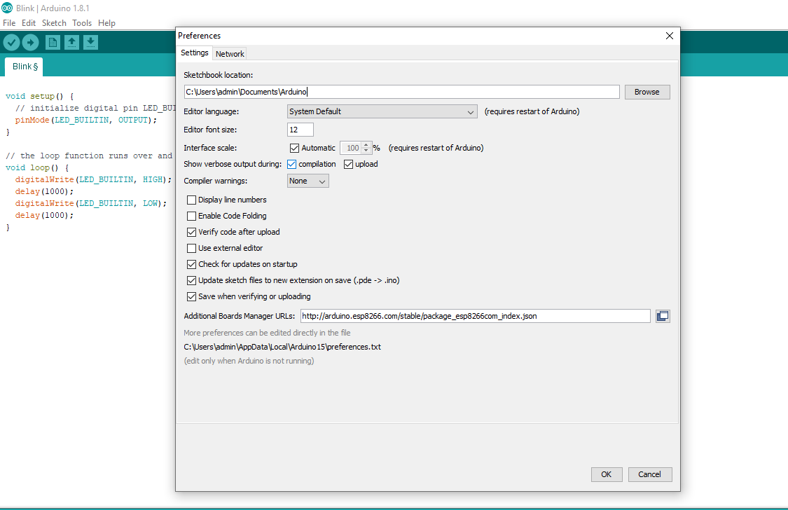
After ticking it, now click on the OK button and this dialog box will close.
Now hit the compile button as we tick the compilation option, so it will compile the code and will give all the commands as shown below:

Now you can see clearly in the above figure that there are many commands in the black portion, these are the verbose output which Arduino is giving us.
The last line of these verbose outputs, which have also highlighted is the link to hex file, which in our case is:
C:\Users\SHREYASH\AppData\Local\Temp\arduino_build_62467/Remote_Control_for_DC_Motor.ino.hex
Paste this link in the computer address bar and this folder will open up.
In that folder search for your respective file and easily get the hex file of your code.
That’s why, don’t get the hex file, but by clicking the option can easily get the hex file and then can use it for any purpose.
Here’s the video in which have shown you How to get the hex file from Arduino
To Download the code click here
2.2.3 Detail Explanation of code
1.Here we need to understand the function pin pinMode( ). Here led is an output device. Arduino will send an output signal to the led. But how to tell the arduino how to signal output or input.
2. To send the output, we make arduino pin 13 as output by using the pinMode(13,OUTPUT). This pinmode function has two arguments.
3. The first argument tells about the pin number where the led connected. So here digital pin 13 connected to the led.
4. The second argument tells how this pin will be used as an input or output. Here it is a led and we want a output at this pin, so make it as output.
5. By using the function pinMode(13, OUTPUT) doesn’t give any output or ON the led. It simply set the pin 13 as in output mode.
6. The actual output will appear at the digital pin 13 by the function digitalWrite( ). This function can give out HIGH or LOW depending on the parameter used in the function.
7. Here a high signal from the digital pin makes the led ON. So the function would be digitalWrite(13, HIGH). And if you want to OFF the led then give a low signal by digitalWrite(13, LOW).
8. The first argument tells about the pin number where the led connected. So here digital pin 13 connected to the led.
9. The second argument tells how this pin will be used as an input or output. Here it is a led and we want a output at this pin, so make it as output.
10. By using the function pinMode(13, OUTPUT) doesn’t give any output or ON the led. It simply set the pin 13 as in output mode.
11. The actual output will appear at the digital pin 13 by the function digitalWrite( ). This function can give out HIGH or LOW depending on the parameter used in the function.
Here a high signal from the digital pin makes the led ON. So the function would be digitalWrite(13, HIGH). And if you want to OFF the led then give a low signal by digitalWrite(13, LOW).
See Also
- setup()
- loop()
- pinMode()
- digitalWrite()
- delay()
2.3 Result:
Published by, Electronics with Shreyash
Join our Community:
- Blogger
- WordPress
- Git Hub
- Telegram Group (Electronics with shreyash bot)
- Facebook Group
- Linkedln
- Facebook Page
- You Tube
